Sand-E Development Process
The step by step process involves designing, building, and refining a robot to achieve its intended function. It includes selecting the right mechanics, electronics, and implement good software
Previous Model
Initially, the robot's mechanics utilized the same rake system with smaller sizes. For the trash collection system, a scoop was used to scrape trash from the sand. Additionally, the robot was not controlled via a controller but operated manually by being pushed.
Groups
To ease workload, the team is divided into three groups
Mechanics
The mechanics group handles the physical parts of the robot.

Electronics
The electronics group handles the connection between software and hardware of the robot.

Software
The software group handles the movements of the robot by programming its behavior using Arduino.
1. Mechanics
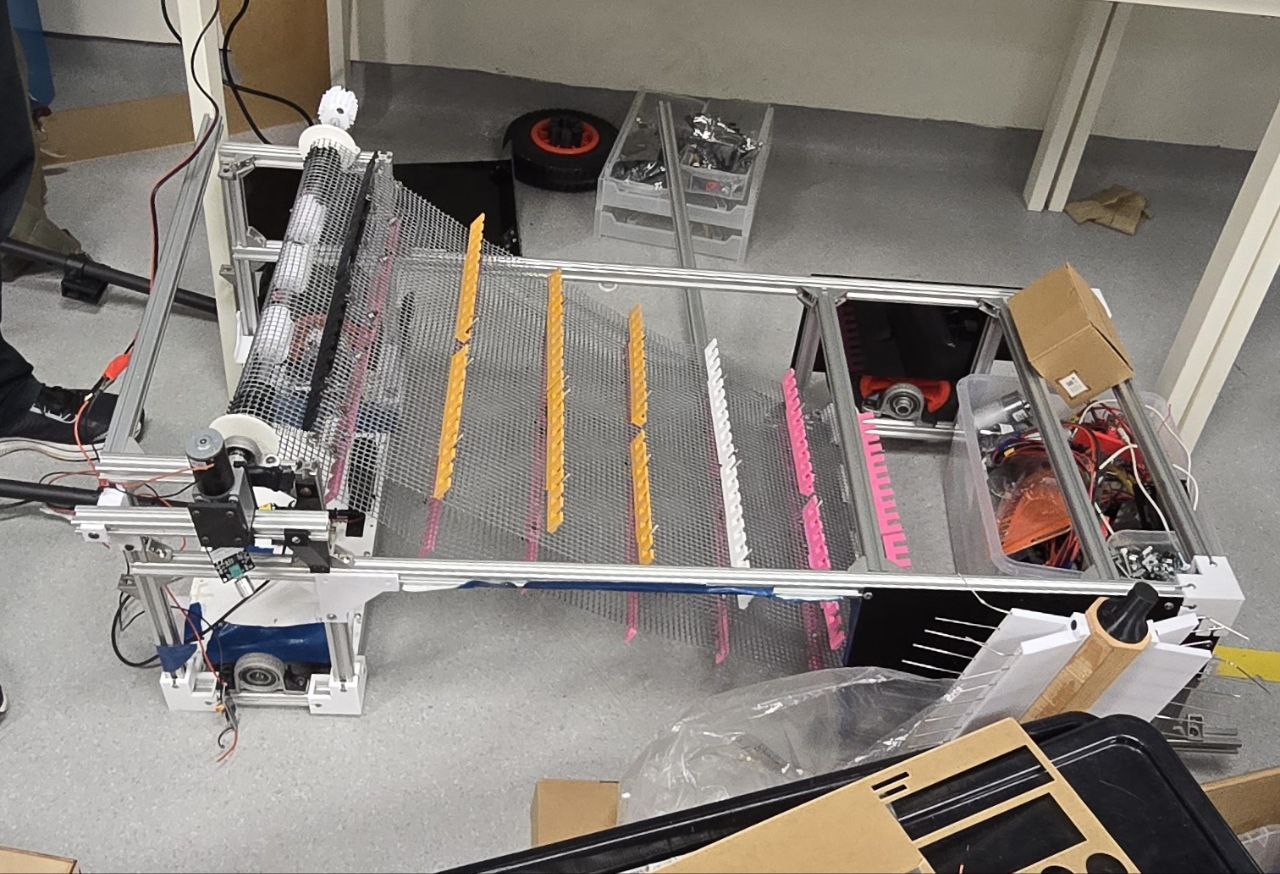
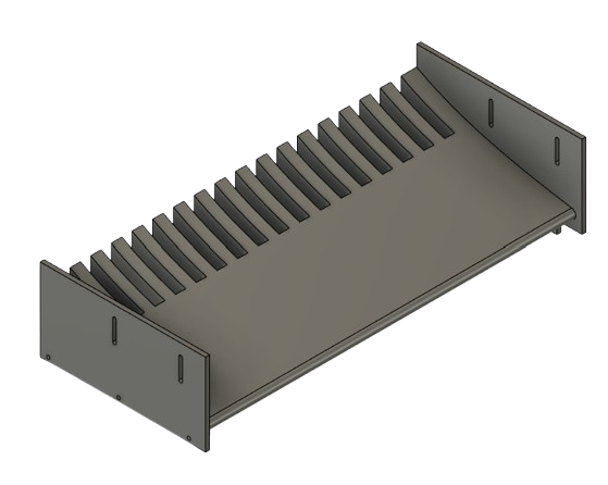
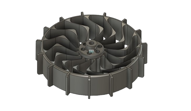
a. Trash Collection System
This system is a part of the robot that works in taking the trash from sand. This prototype was designed using fusion 360 and printed with bamboo 3d printer.
Initial Designs
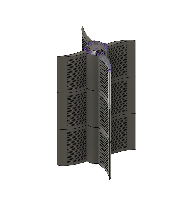
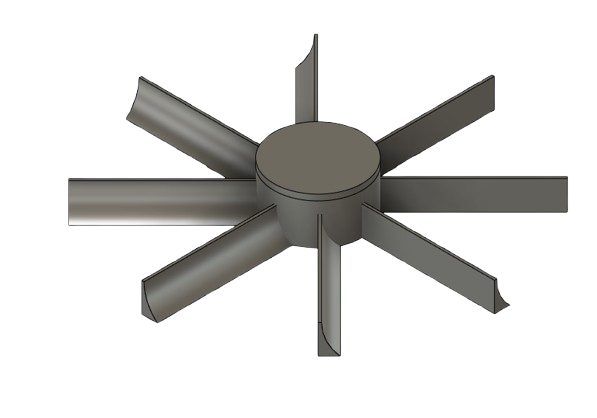
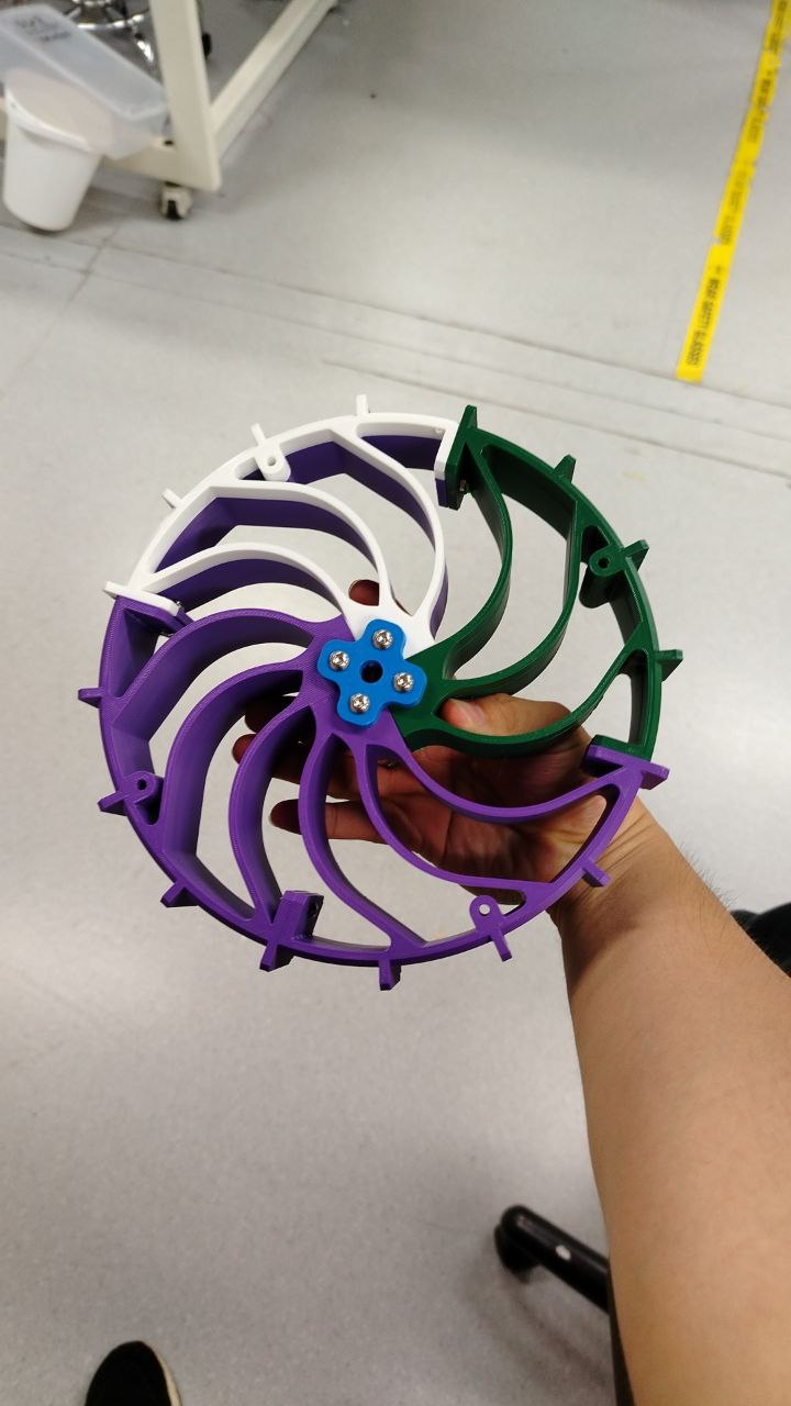
Feeder
This design was picked and modified to weigh less to reduce filament usage. The middle part of the fan was also modified with zip ties to be more elastic
Scoop
This design was not used due to limited motor power
Rotating Brush
The software group handles the movements of the robot by programming its behavior using Arduino.
Challenges
- Feeder's fins are not long enough or shaped properly to take the trash
-Trash does not go up to the conveyer belt
-Rounded sides due to spinning
Our Solution
- Modifiy the model of the fins to enable it to be attached with zipties that are flexible and long that allows easier trash collection.
- Modify the rakes to have a bigger scope and attach more 3 rakes in rows of conveyer belt.
- The sides are secured with a metal screw mechanism to minimize rounding
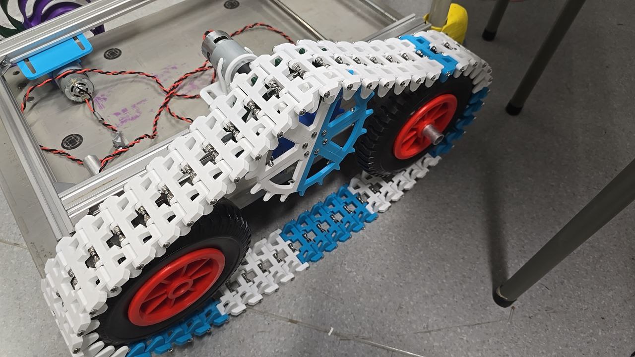
b. Continuous Tracks
This system enables the robot's mobility, allowing it to move forward, backward, left, and right. The addition of tracks helps prevent it from sinking into the sand, ensuring smoother movement.
Challenges
- Tracks can not connect without long screws
- Wheel keeps slipping off the track
- The tension is too high for the flywheel that is connected to the motor
- The connection from the flywheel to the motor keeps rounding
- The tracks are too heavy for the motor
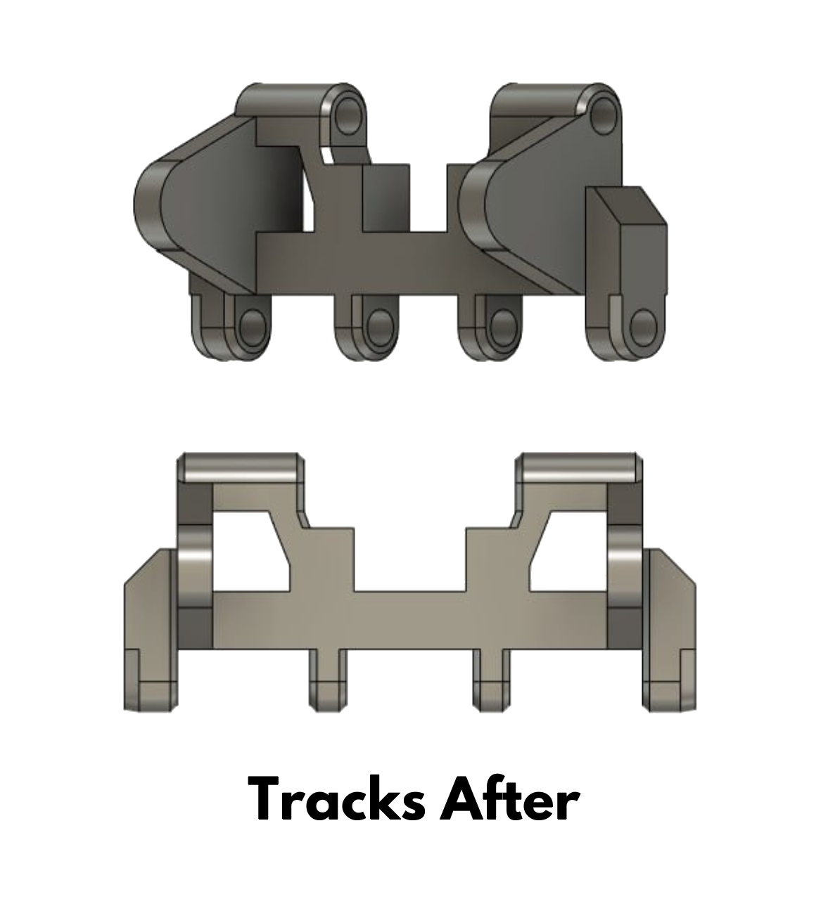
Our Solution
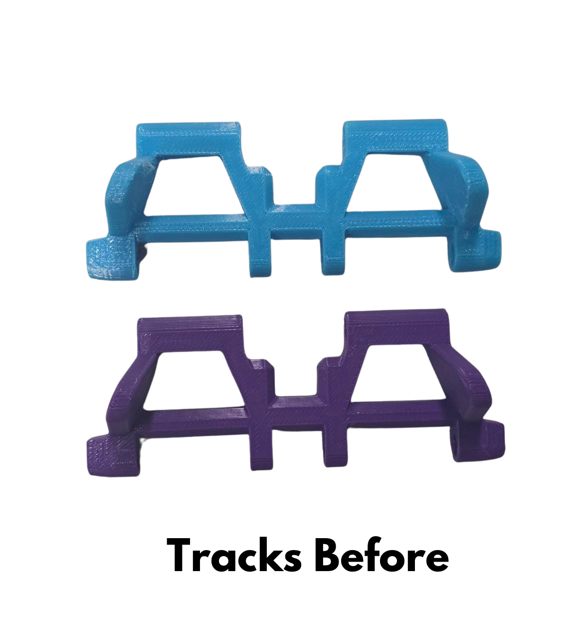
- Change design of tracks with two screws to connect the pieces
- Extend the design to cover the sides of the track, preventing the wheels from veering off, especially during turns
- Segment the flywheel into multiple pieces and secure them using screws and nuts
- Change the connection to metal to minimize rounding
- Make the design simpler and round the edges
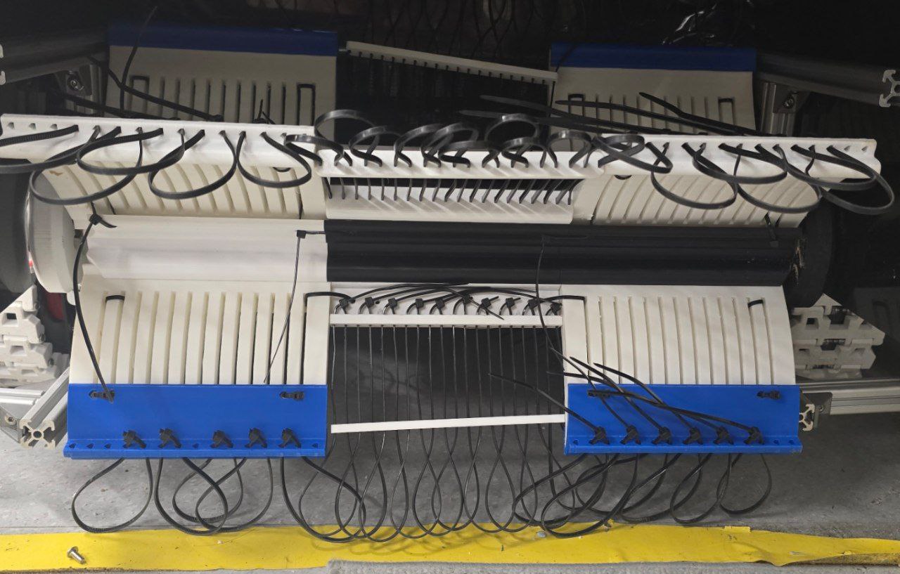
c. Balloon Wheels
The concept of the balloon wheels was to be contented with the continuous tracks on what would be the main method of movement for the robot itself. Whilst in development, the wheels were ultimately to be used to be a back up plan in the event that the tracks were to break down in the midst of operation.
For the most part, our main challenge was allocating sufficient time for both the robot’s development and its construction. A more specific challenge related to the wheels was the difficulty of implementing the "balloon" aspect due to limited funding. To address this, we attempted to substitute it by incorporating a compliant mechanism into the wheel. Additionally, the balloon wheels group developed a backup plan in case the main robot track system failed.
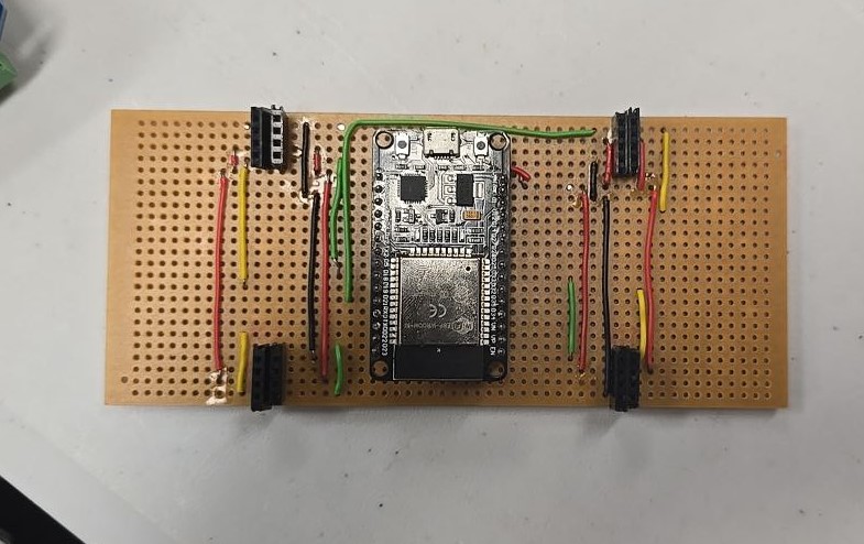
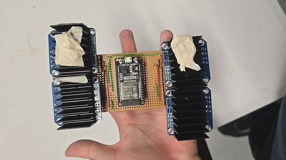
2. Electronics
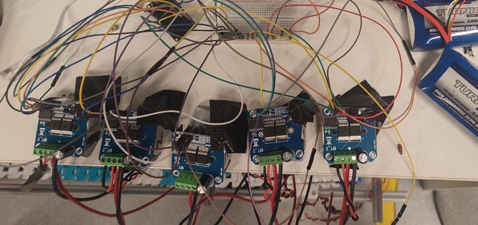
The electronics team in a robot project handles motor control, power management, and sensor integration. They design PCBs to simplify wiring, ensure safety, and optimize performance, bridging the mechanical and software components for smooth operation.
Challenges
- Soldering components, preventing overheating, and ensuring smooth integration between hard and software.
- The layout of the components, wiring, and ESP32-S3 was a challenge. The electronics needed to be well-distributed to accommodate the motors, which were positioned far apart.
Our Solution
- To address soldering issues, I used an adjustable-temperature soldering iron, heat shrink tubing, and soldering flux to ensure secure and durable connections.
- Power distribution was managed through the use of voltage regulators and dedicated power boards, ensuring each component received the appropriate voltage. By understanding the schematics of the different components, I was able to break down the different usages and identify ways of troubleshooting. The Arduino and ESP32 boards were used for their versatility and processing power in handling the robot's tasks.